Showing posts with label 3rd semester. Show all posts

Speaker Recognition using Matlab

Ø ABSTRACT:
           ·        The project recognizes the input data spoken by the speaker by comparing it with the reference data.
·        It involves having Fast Fourier transform of the given speech then normalizing the frequency signal.

           ·        Finally, the reference and the given data are compared and the result is displayed depending on the variation in the input speeches. 

Ø WORKING OF MODEL: 


Ø MATLAB CODING:
Ø  Coding for Input:-
data=data(1:600);
fy=fft(data);
fy=fy.*conj(fy);
tn=fy/sqrt(sum(abs(fy).^2));

Ø  Coding for Comparasion:-
s=sqrt(sum(abs(f-d).^2));
if s<2*1
    result=strcat('HELLO!!!');
    result
else
    result=strcat('YOU ARE NOT');
    result
end

Continue Reading

OPTO-THERMO CONTROL RELAY SWITCH

1.  ABSTRACT:
Ø The circuit shows the working of opto-control switch, where LDR is used as a switch to open and close the circuit.
Ø 555 timer IC is used as a comparator.
Ø The product of RC is used to produce the delay in the IC and affects pulse propagation through it.
2.  COMPONENTS:
Ø Resistors (1k,47k,10k)
Ø Capacitors (2*.01uF, 1*4.7uF)
Ø IC LM555
Ø LDR (500 ohms)
Ø Speaker (8 ohms)
Ø Battery 9V

3.  CIRCUIT DIAGRAM:


Ø In P-Spice:
4.  OUTPUT RESPONSE:
Ø When Light is not falling on LDR:
·        Voltage:-
·       Current:-

Ø When Light is falling on LDR:
·       Voltage:-

·       Current:-

5.  APPLICATIONS:
Ø Used in parking system. When the car comes near the gate of garage, the parking lamp glows and the gate opens as the light falls on the LDR and the current passes through the circuit.
Ø Security alarm 


Continue Reading

ANALYSIS OF CHARACTERSTICS OF 3-PHASE INDUCTION MOTOR

            1.     INTRODUCTION:
v A 3-phase induction motor consists of a stator and rotor.
v The stator carries a 3-phase winding (called stator winding) while the rotor carries a short circuited winding (called rotor winding).
v Only the stator winding is fed from 3-phase supply. 
vThe rotor winding derives its voltage and power from the externally energized stator winding through electromagnetic induction.

2.  COMPONENTS OF INDUCTION MOTOR:
1.) Rotor..
     v  The rotor, mounted on a shaft, is a hollow laminated core having slots on its outer periphery.
     v The winding placed in these slots (called rotor winding) may be one of the following two type :
¡  (i) Squirrel cage type
¡  (ii) Wound type
2.)Stator..
v It consists of a steel frame which encloses a hollow, cylindrical core made up of thin laminations of sili­con steel to reduce hysteresis and eddy current loss.
v A number of evenly spaced slots are provided on the inner periph­ery of the laminations.
v The insulated conductors are placed in the stator slots and are suitably connected to form a balanced 3-phase star or delta connected circuit.

3.  WORKING OF INDUCTION MOTOR:
v When the stator windings are connected to a three-phase power supply and rotor circuit is closed, the induced voltage in the rotor windings produce rotor currents that interact with the air gap field to produce torque.
v Rotor, if free to do so, will start rotating.
v This field is such that its poles do not remain in a fixed position on the stator but go on shifting their positions around the stator.

4.  THE VARIOUS METHODS OF SPEED CONTROL OF 3-PHASE INDUCTION MOTOR:

v Pole Changing
v Variable Supply Frequency
v Variable rotor resistance control
v Variable supply voltage control
5.  ADVANTAGES OF 3-PHASE INDUCTION MOTOR:

v It has simple and rugged construction.
v It is relatively cheap.
v It requires little maintenance.
v It has high efficiency and reasonably good power factor.
v It has self-starting torque.
v In fractional-horsepower (less than 1hp) applications, the single-phase motor will be less efficient.

 6. BLOCK DIAGRAM in SIMULINK: 


7. BLOCK PARAMETERS:


8. MATLAB-SIMULINK ANALYSIS:
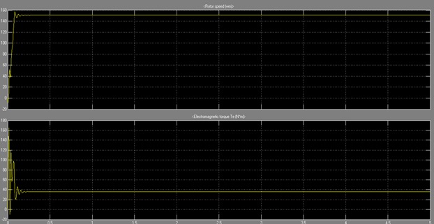
  ØROTOR SPEED(rad./sec.) and ELECTROMAGNETIC TORQUE(N*m)
§  @(415V ,50 Hz )3-phase Voltage Supply


  ØSTATOR CURRENT(A) and ROTOR CURRENT(A)
§  @(415V ,50 Hz )3-phase Voltage Supply


  ØSTATOR CURRENT(A) and ROTOR CURRENT(A)
§  @(415V ,60 Hz )3-phase Voltage Supply


  Ø ROTOR SPEED(rad./sec.) and ELECTROMAGNETIC TORQUE(N*m)
§  @(415V ,60 Hz )3-phase Voltage Supply


Continue Reading

SIGNAL AMPLIFIER

1.  ABSTRACT:
The circuit shows a 3-transistor voltage amplifier suitable for a variety of projects including receivers, intercoms, microphones, telephone pick-up coils, and general audio monitoring. The values are not particularly critical and modest deviations from the indicated values will not significantly degrade the performance.

2.  COMPONENTS:
·       Resistors
·       Capacitors
·       Transistors(Q2N2222)
·       Voltage Supply(DC)
·       Input Voltage(Vsin)

3.  WORK OF EACH COMPONENT:
·       Resistors:
In the given circuit resistor R5 is working as an Rs. It is also used to improve amplifier. R6 and R7 have such a high resistance values, so that whole current which is coming from source go to the base of the Q2. R10 and R11 also have high resistance values for same reason. R12 is Rc(collector resistance) of Q3 and R13 is Re(emitting resistance) of Q4. R14 is load resistance.

·       Capacitors:
Capacitors are used for pass the AC current and block the DC current. C5, C6 and C8 are working to prevent the ac current to directly hit the DC supply.

·       Transistors:
All the 3 npn transistors work to amplify and stabilize the input signal. 

·       Voltage Supply(DC):
Dc supply is given to put all the Transistors into cut-off region.

·       Input Voltage(Vsin):
To give the minute input sinusoidal signal.


4.  CIRCUIT DIAGRAM:


5.  WORKING OF CIRCUIT DIAGRAM:
A minute sinusoidal wave is given to Q2 which is brought into cut-off region by Vdc and hence amplifies the signal. The signal then is carried forth to the next pair of transistors which stabilize, modulate and further amplify the signal the output at the emitter of Q4 is fed to C9 which across the R14 is the final output.

6.  OUTPUT RESPONSE:


Red: Input
Green: Output


7.  APPLICATION:
Voltage amplifiers can be used in various fields. Among them some are given below:
·       Receivers
·       Intercoms
·       Microphones
·       Telephone pick-up coils
·       Mobile phones
·       General audio monitoring

Continue Reading

5-BIT PARALLEL ADDER

Abstract:

Ø The use of one half-adder or one full-adder alone is good for add two binary numbers with a length of one bit each. 
Ø But what happens when we want to add two binary numbers with a longer length? 
Ø So, there are many ways to do this. The fastest and easy way by far is to use the Ripple Carry Adder or Parallel Binary Adder.
Ø Parallel Binary Adder uses one half-adder along with one or more full adders depends on the length of the two binary numbers that are to be added.
Ø It is also called as “Ripple Carry Adder”.


You can understand it easy by following block diagram.


Block Diagram:


Circuit Diagram:


Truth table for half adder:


Truth table for full adder:


Software implementation using “Virtual Digital Simulator”:


Inputs are "10110" and "11011"
Output (sum) is "110001"
Cout is "1"
c0, c1, c2, c3 are 0,1,1,1 relatively


ICs used in the project:

OR GATE IC: 74LS32
AND GATE IC: 74LS08
XOR GATE IC: 74LS86


Continue Reading